
 EN
EN
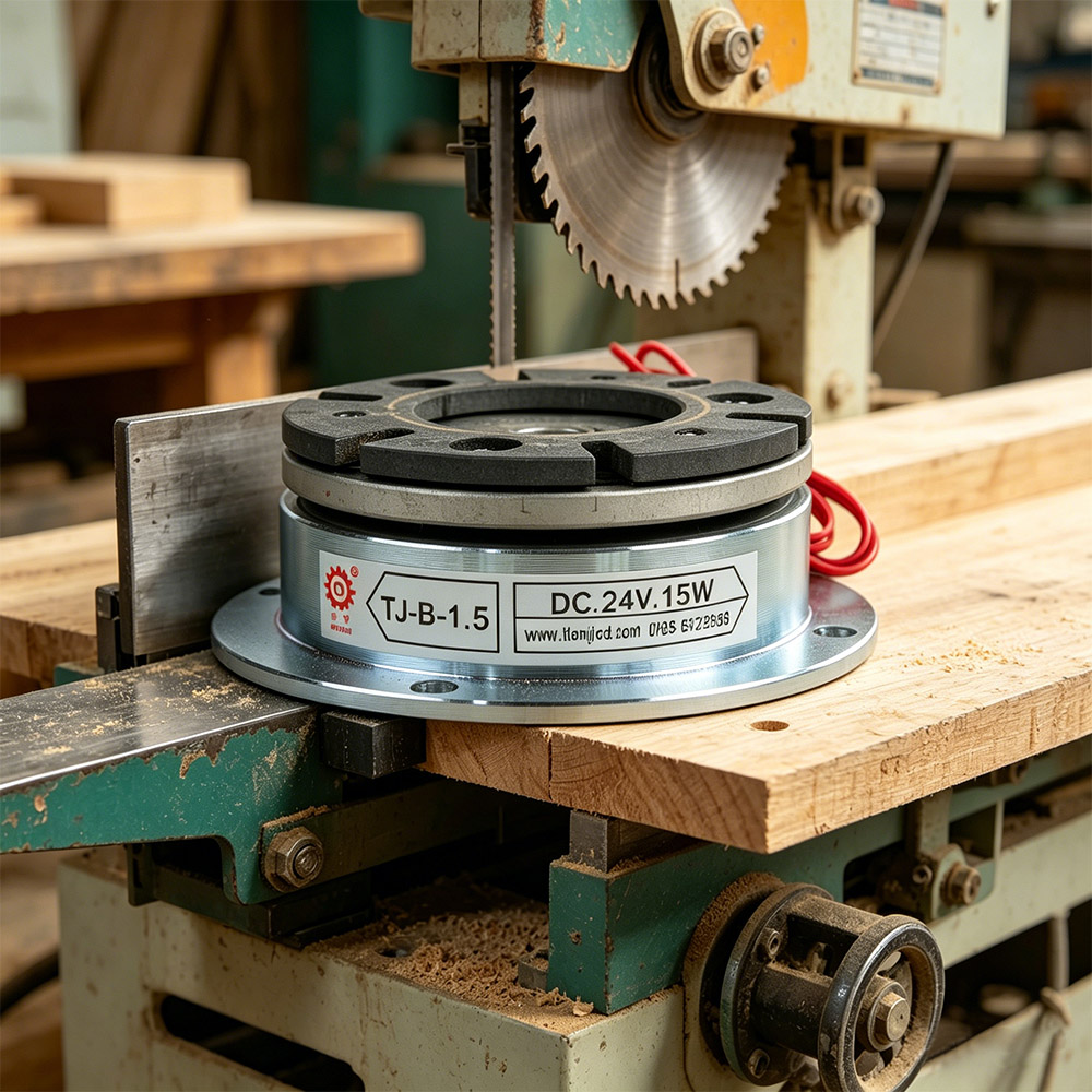
Selecting the correct electromagnetic brake for your original equipment manufacturing application requires understanding torque demands, duty cycles, environmental conditions, and integration constraints. An electromagnetic brake serves as a critical safety and operational component in conveyor systems, lifting machinery, printing presses, packaging equipment, and automated industrial platforms. The right choice balances performance reliability, cost efficiency, and long-term maintenance requirements, while the wrong selection can lead to unexpected downtime, safety hazards, and costly redesigns.
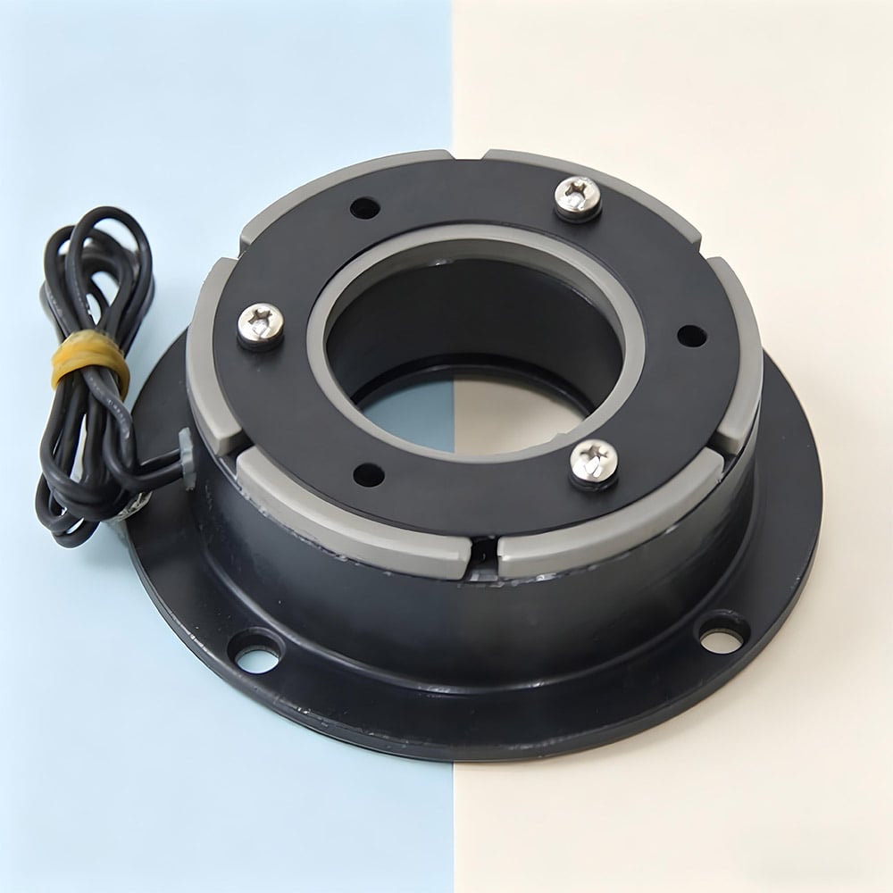
OEM engineers face specific pressure when specifying an electromagnetic brake because the component must integrate seamlessly with existing motor couplings, control systems, and mechanical architectures. Unlike aftermarket retrofits, OEM-level electromagnetic brake selection demands precision in voltage compatibility, mounting geometry, response time, and thermal management. This guide walks you through the critical evaluation criteria and decision factors that separate adequate brake performance from optimized system reliability.
Understanding Electromagnetic Brake Fundamentals for OEM Applications
Core Operating Principles and Duty Classifications
An electromagnetic brake operates by applying magnetic force to engage a friction disc against a rotating shaft or coupling hub. When power is removed, spring force or gravity engages the brake, stopping rotation. This fail-safe characteristic makes an electromagnetic brake essential for safety-critical applications. OEM specifications distinguish between spring-applied brakes (engage on power loss) and spring-release brakes (disengage on power loss), each suited to different machinery functions. Understanding this fundamental distinction is the first step in proper electromagnetic brake selection.
Duty cycle classification directly impacts electromagnetic brake longevity and safety margins. Continuous duty brakes handle repeated engagement-disengagement cycles with modest thermal load. Intermittent duty electromagnetic brake components tolerate higher per-cycle heat dissipation but require longer cooling intervals. OEM applications like automated packaging lines often run 16-24 hour cycles, demanding electromagnetic brake designs rated for continuous duty operation with heat dissipation analysis built into the selection process.
Voltage and Control System Compatibility
Industrial systems operate on multiple voltage standards: 12V DC, 24V DC, 48V DC, 115V AC, and 230V AC represent the most common offerings. Your electromagnetic brake coil voltage must match your control logic supply precisely. Oversized or undersized voltage creates operational problems—insufficient coil current delays brake engagement, while excessive voltage generates heat and reduces component life. Many OEM designers overlook that electromagnetic brake voltage selection interconnects directly with safety PLC logic, soft-starters, and variable frequency drives. Verify that your chosen electromagnetic brake aligns with existing control infrastructure before finalizing specifications.
Critical Performance Parameters for Electromagnetic Brake Selection
Torque Rating and Load Calculation Methodology
Torque capacity represents the most frequently misunderstood parameter in electromagnetic brake selection. Published torque ratings indicate the maximum braking force under ideal conditions, but OEM engineers must account for duty cycle derating, temperature rise, friction surface degradation, and shock loads. A 50 Newton-meter electromagnetic brake specified for peak load application should only consume 60-70% of its rated capacity under continuous operation. Conservative engineers apply 50% safety factors when selecting electromagnetic brake torque, ensuring adequate performance across thermal cycles and friction material aging.
Shock load analysis becomes critical for vertical lifting or sudden stop applications. An electromagnetic brake holding a suspended load experiences impact loads when the load suddenly transfers. This dynamic stress exceeds static torque calculations and requires oversized electromagnetic brake specifications. Similarly, high-speed rotating equipment demands fast response electromagnetic brake designs that minimize stopping distance under emergency conditions. Engineers often request electromagnetic brake models with dual-stage coils or shortened air gaps to achieve sub-100 millisecond response times in safety-critical machinery.
Response Time and Thermal Management Requirements
Response time—measured from electrical signal to full braking force—directly affects machinery safety and production efficiency. A 200-millisecond delay in electromagnetic brake engagement might allow dangerous blade travel in a press, or excess overshoot in a conveyor positioning application. OEM specifications increasingly demand electromagnetic brake response times under 150 milliseconds, requiring optimized coil designs and minimal mechanical friction in the engagement mechanism. Verify published response times under actual operating voltage and load conditions, as degraded coil insulation or worn friction surfaces extend electromagnetic brake engagement time progressively during equipment life.
Thermal dissipation capacity determines how many duty cycles an electromagnetic brake can handle before friction surface degradation compromises performance. Each braking event generates heat proportional to torque and stopping distance. An electromagnetic brake specified for 50 stops per hour experiences different thermal stress than one handling 500 stops per hour. Industrial thermal analysis calculates permitted surface temperature rise and compares it against friction material specifications. Electromagnetic brake designs with large friction surface area, aluminum housings, and cooling fins dissipate heat more effectively than compact designs, making them superior choices for high-duty applications despite higher initial cost.
Integration Considerations and Environmental Factors Affecting Brake Selection
Mechanical Mounting and Coupling Interface Requirements
OEM integration of an electromagnetic brake demands precise mechanical matching between brake shaft diameter, keying systems, and mounting flange geometry. Misaligned electromagnetic brake installations create runout vibration, accelerated bearing wear, and inconsistent braking torque application. Modern electromagnetic brake designs offer multiple mounting configurations: inline shafts, foot mounts, flange mounts, and custom interfaces. Specify mounting geometry during the selection phase rather than attempting to adapt incompatible interfaces in production. Many OEM problems trace back to assumptions about standard electromagnetic brake mounting dimensions that prove incorrect during integration testing.
Coupling the motor drive to the electromagnetic brake requires matching torque transmission capacity. Direct coupling works for low-speed applications, while belt or gear reduction may be necessary for high-speed motors. The selected electromagnetic brake must tolerate transmitted torque without slipping or generating excessive heat. Elastomeric couplings absorb vibration but introduce compliance that affects electromagnetic brake response consistency. Rigid couplings transmit shock loads directly to electromagnetic brake friction surfaces. OEM designers balance coupling stiffness against electromagnetic brake shock load capacity during mechanical system architecture decisions.
Environmental and Contamination Protection Strategies
Industrial environments expose electromagnetic brake components to moisture, dust, oil mist, and chemical residues that degrade electrical insulation and friction surfaces. An electromagnetic brake rated IP54 (dust and splash protection) suits sheltered mounting in climate-controlled cabinets. However, electromagnetic brake applications in food processing, chemical plants, or outdoor equipment demand higher protection ratings and special surface treatments. Stainless steel friction discs resist corrosion better than standard steel, while sealed coil covers prevent moisture ingress that causes electrical shorts. IP67-rated electromagnetic brake designs with conformal coatings provide maximum environmental robustness for harsh-duty OEM machinery.
Oil contamination represents a silent killer of electromagnetic brake performance. Even light oil film on friction surfaces reduces torque transmission by 30-50%, rendering brake capacity calculations invalid. Gearbox location relative to electromagnetic brake installation matters significantly—splash lubrication gearboxes release aerosol oil that settles on adjacent components. Sealed brake housings and remote mounting away from oil sources preserve electromagnetic brake friction surface cleanliness. Some OEM designers specify electromagnetic brake cleaning procedures in maintenance protocols, but prevention through design always outperforms reactive cleaning schedules.
FAQ
What torque margin should I apply when selecting an electromagnetic brake for OEM equipment?
Industry best practice recommends applying a 50-60% safety factor to your calculated maximum brake torque requirement. This conservative approach accounts for friction surface wear, thermal derating, shock loads, and control signal variations over equipment life. An electromagnetic brake sized for 100% of peak load will gradually lose effectiveness as friction material ages, eventually becoming undersized by year three of operation. Selecting electromagnetic brake capacity at 150% of calculated need ensures reliable performance across the entire equipment service life without unexpected brake degradation or safety compromises.
How do I verify that an electromagnetic brake will integrate with my existing motor and control system?
Confirm four critical compatibility points before finalizing electromagnetic brake selection: voltage matching between brake coil and control supply, mechanical shaft and mounting dimensions matching your motor coupling interface, response time meeting your safety system requirements, and thermal management capability matching your duty cycle. Request detailed CAD drawings and dimensional specifications from electromagnetic brake manufacturers, then overlay them against your motor drawings and control architecture documentation. Prototype testing of the complete electromagnetic brake assembly with your actual motor and PLC logic remains essential, as electrical interference or mechanical resonance sometimes emerges only during integrated system operation.
What maintenance schedule should electromagnetic brake components follow in OEM production equipment?
Establish electromagnetic brake inspection intervals based on duty cycle—equipment operating 8 hours daily needs annual inspection, while continuous-duty systems require semi-annual checks. Inspect friction surface wear depth using precision calipers and compare against manufacturer wear limits; if remaining friction material thickness falls below specified minimums, replace the brake assembly before catastrophic failure occurs. Test coil electrical resistance and megohm insulation readings annually to detect degradation early. Document response time performance using electrical test equipment; slowing response indicates friction surface deposits or mechanical wear requiring attention. Proper electromagnetic brake maintenance prevents unexpected failures that disrupt production and create safety hazards.

