
 EN
EN
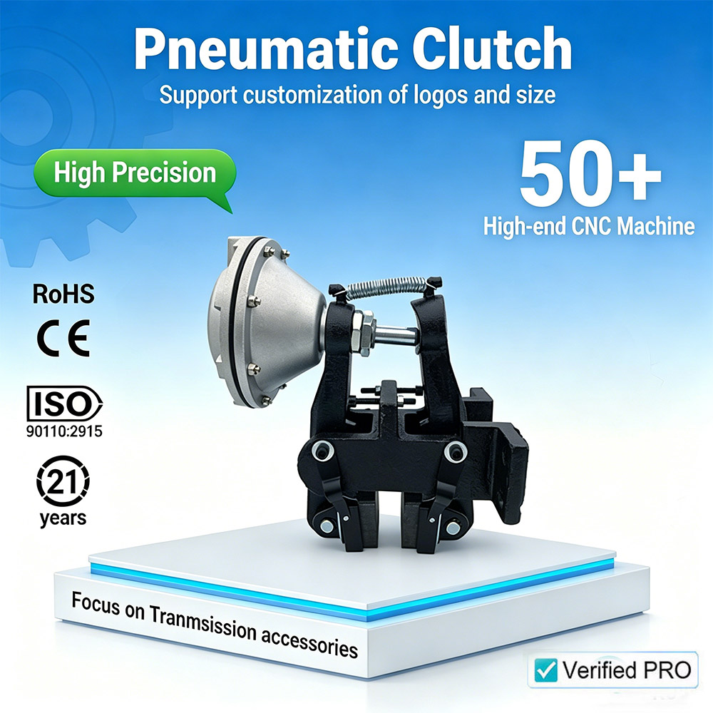
Industrial pneumatic brakes rely on precise torque output to ensure safe equipment operation and consistent stopping performance across manufacturing environments. The air shaft serves as the central mechanical component that directly translates pneumatic pressure into rotational braking force, making proper adjustment of this component essential for both safety and operational efficiency. Understanding how to calibrate and modify air shaft settings allows maintenance teams and engineers to fine-tune braking systems without requiring complete component replacement or extensive downtime.
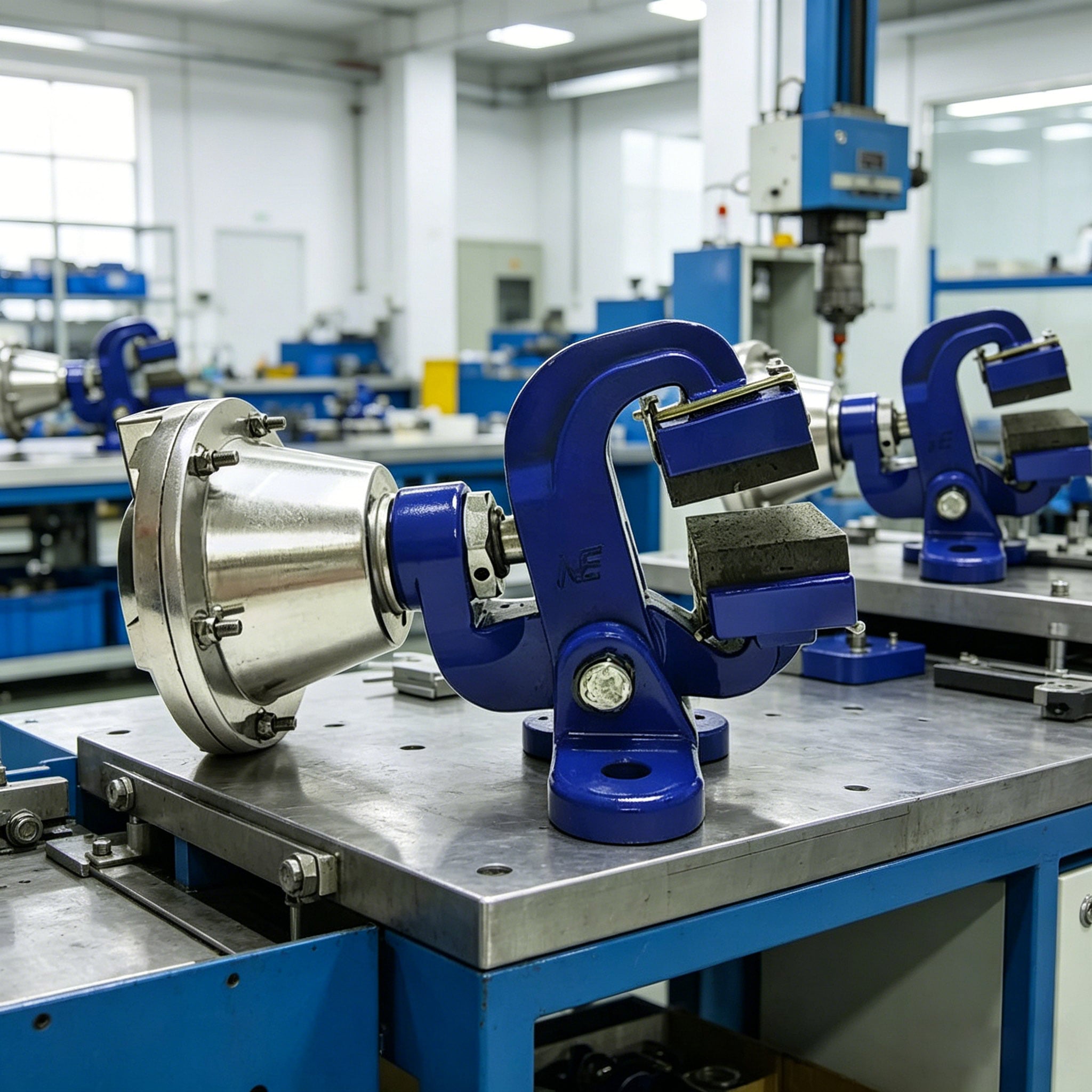
Torque adjustment on industrial pneumatic brakes fundamentally depends on regulating air pressure delivery and mechanical leverage through the air shaft mechanism. When facility managers need to modify braking torque output, they must understand both the pneumatic principles governing pressure conversion and the mechanical design of the air shaft itself. This knowledge base enables operators to respond quickly to changing production demands, accommodate different load conditions, and maintain compliance with industry safety standards without external service calls.
Understanding Air Shaft Function in Brake Torque Control
The Role of Air Shaft in Pneumatic Brake Systems
The air shaft represents the direct interface between pneumatic actuators and the braking mechanism in industrial systems. This shaft rotates when pneumatic pressure activates the brake actuator, and its rotational force directly translates into clamping pressure on brake discs or friction surfaces. The mechanical geometry of the air shaft, including its diameter, bearing surfaces, and connection points, determines the mechanical advantage ratio that converts pneumatic force into torque output. Understanding air shaft design characteristics helps technicians identify which adjustment parameters will most effectively modify overall brake performance.
Pressure-to-Torque Conversion Mechanics
Pneumatic brakes convert compressed air pressure into rotational torque through a mechanical advantage system centered on the air shaft. When air pressure enters the actuator chamber, it pushes against pneumatic pistons or diaphragms that are mechanically linked to the air shaft. The air shaft then rotates to engage brake calipers or apply friction materials against rotating surfaces. The mathematical relationship between input air pressure and output torque depends directly on the effective area of pneumatic surfaces acting on the air shaft and the mechanical leverage ratio built into the brake assembly. Increasing air shaft diameter or improving pressure delivery efficiency increases torque output, while reducing these parameters decreases braking force.
Primary Methods for Adjusting Torque Output
Regulating Supply Air Pressure
The most straightforward approach to adjusting air shaft torque output involves modifying the compressed air pressure supplied to the brake system. Industrial facilities typically maintain a consistent baseline air pressure from their compressor network, but brake-specific regulators allow technicians to adjust pressure at each individual brake unit. Installing a secondary pressure regulator downstream of the main air line enables fine-tuning of pressure delivery to the brake actuator. By increasing pressure, the air shaft experiences greater pneumatic force, resulting in higher torque output and stronger braking action. Conversely, reducing supply pressure proportionally decreases the rotational force generated by the air shaft. Most industrial pneumatic brakes operate effectively across a 40 to 90 PSI range, though specific models may have narrower operating windows requiring consultation with equipment specifications.
Mechanical Leverage Modification
Beyond air pressure adjustments, the mechanical leverage characteristics that influence air shaft performance can be modified through component selection and positioning. Some brake designs feature adjustable mechanical linkages between the pneumatic actuator and the air shaft, allowing technicians to alter the force multiplication ratio. Relocating pivot points or adjusting the effective length of mechanical arms connecting to the air shaft changes the mechanical advantage, thereby modifying the torque transferred to the brake mechanism. These modifications require detailed understanding of the specific brake model and should only be performed by qualified technicians following manufacturer guidelines. Incorrect mechanical adjustments can compromise brake safety or reduce system reliability.
Maintenance and Performance Monitoring for Optimal Air Shaft Function
Regular Inspection Protocols
Maintaining consistent and reliable torque output requires systematic inspection of air shaft components and the surrounding brake assembly. Technicians should regularly examine the air shaft for signs of scoring, corrosion, or wear that could affect rotational smoothness and force transmission. Bearing condition directly impacts how efficiently pressure converts to torque, so lubrication and bearing clearance must be verified regularly. Any debris accumulation, air leaks in the actuator chamber, or valve deterioration will reduce the effective pressure reaching the air shaft, thereby lowering torque output unexpectedly. Establishing a preventative maintenance schedule that includes air shaft inspection, pressure testing, and functional validation helps identify degradation before brake performance becomes compromised.
Testing and Calibration Procedures
After adjusting torque output parameters on the air shaft or related components, testing procedures confirm that modifications achieved the intended results. Torque measurement devices connected to the brake output can provide quantitative validation of braking force. Many facilities employ load cell testing or dynamometer-based systems to verify that adjusted air shaft torque output meets production requirements and safety standards. Functional testing should include repeated brake cycles under representative load conditions to confirm that torque consistency remains stable and that no safety concerns emerge. Documentation of all adjustment procedures and test results creates a maintenance record that supports troubleshooting if performance issues arise later.
FAQ
What factors most significantly impact air shaft torque output adjustment?
Supply air pressure and the mechanical leverage characteristics of the brake assembly represent the two primary factors controlling air shaft torque output. Pressure adjustments typically provide the quickest and most reversible modifications, while mechanical changes offer more permanent performance tuning. The pneumatic actuator design, bearing condition, and seal integrity also substantially influence how effectively pressure translates into usable torque from the air shaft.
Can air shaft torque adjustments be made without shutting down production equipment?
Pressure regulation adjustments to the air shaft control system can often be performed safely on equipment in a stationary state without full system shutdown, provided all pneumatic energy is isolated and properly dissipated. Mechanical modifications to the air shaft or brake linkage typically require full isolation and lockout-tagout procedures to prevent accidental equipment operation. Always follow facility safety protocols and manufacturer recommendations before adjusting any brake-related components.
How often should air shaft torque output be verified?
The frequency of air shaft torque verification depends on equipment usage intensity, environmental conditions, and regulatory requirements specific to your industry. Most facilities verify brake torque output quarterly or semi-annually as part of routine preventative maintenance, with additional testing following any mechanical repairs or torque adjustments. Critical safety applications may require monthly verification or continuous monitoring through integrated sensors on the air shaft assembly.

