
 EN
EN
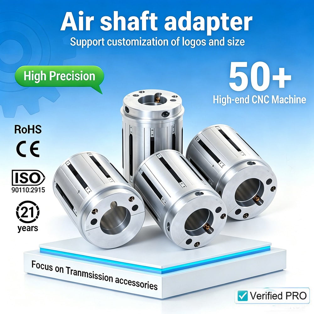
Continuous slipping applications demand precision, reliability, and thermal management that standard braking systems cannot deliver. An air shaft represents a critical innovation in pneumatic brake technology, specifically engineered to handle sustained slip conditions without overheating or performance degradation. Industrial operations involving web tension, material unwinding, and dynamic load control rely on air shaft braking systems to maintain consistent performance across extended operational cycles. Understanding how an air shaft functions within modern pneumatic brake design is essential for engineers and operators selecting equipment for demanding slip-control applications.
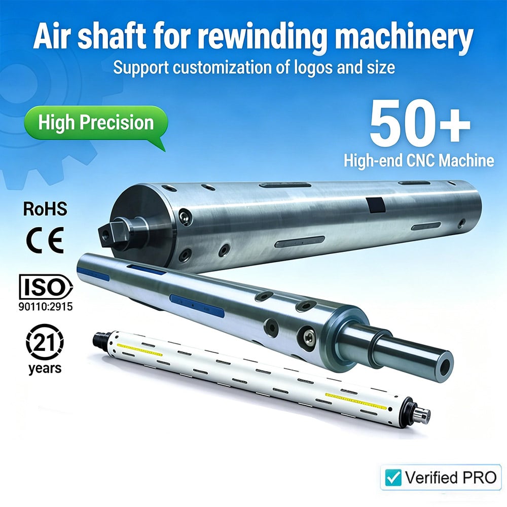
The integration of cooling mechanisms into an air shaft brake assembly addresses the heat generation inherent to continuous slipping operations. Traditional magnetic or friction brakes experience thermal stress during prolonged slip events, potentially leading to component fatigue and reduced service life. Air-cooled pneumatic brakes leverage forced air circulation around the air shaft rotor and stator to dissipate heat efficiently, maintaining optimal operating temperatures and ensuring stable braking torque throughout extended runtime. This thermal management capability transforms continuous slipping from a maintenance challenge into a manageable, predictable industrial process.
The Role of Air Shaft in Pneumatic Brake Systems
Core Functionality and Design Principle
An air shaft serves as the rotating component within a pneumatic brake assembly, directly interfacing with the load-carrying mechanism of machinery. The air shaft rotates with the driven equipment, experiencing the full force of dynamic slip conditions while transferring controlled braking torque back to the system. Modern air shaft designs incorporate hollow passages or channels that allow pressurized air to flow through the rotating element, creating both braking effect through magnetic or eddy-current interaction and continuous cooling as air circulates. This dual-function design distinguishes advanced air shaft brakes from stationary brake systems, enabling them to handle demanding slip-control roles in web handling, paper production, textile manufacturing, and similar industries.
Thermal Management Through Air Circulation
Heat generation during continuous slipping occurs because kinetic energy converts to thermal energy within the air shaft brake gap. An air shaft with integrated cooling passages draws ambient air through sealed ports, forcing it across heated surfaces of the rotor and stator assembly. The circulating air absorbs thermal energy continuously, preventing temperature accumulation that would otherwise degrade brake performance or shorten component lifespan. This active cooling mechanism allows an air shaft brake to operate at slip speeds and duty cycles that would overheat conventional stationary brakes, making air-cooled technology the preferred choice for 24/7 industrial operations where continuous slipping is unavoidable.
Engineering Advantages of Air-Cooled Air Shaft Brakes
Precision and Consistency in Load Control
Industrial tension control applications depend on braking systems that maintain consistent torque output across varying slip speeds and thermal conditions. An air shaft brake designed with air cooling maintains stable magnetic or eddy-current braking characteristics because the air shaft temperature remains controlled within a narrow operating window. Temperature stability directly translates to predictable braking force, allowing operators to fine-tune tension parameters without frequent manual adjustments. For applications such as web unwinding in paper or textile manufacturing, an air shaft system delivering consistent slip control reduces material waste, improves product quality, and minimizes operator intervention during production runs.
Extended Component Life and Reduced Maintenance
Thermal stress accelerates wear on brake components, leading to premature failure and unplanned downtime. An air shaft brake incorporating active air cooling extends the operational life of magnetic coils, eddy-current conductors, bearing assemblies, and seal materials by maintaining lower average operating temperatures. Reduced thermal cycling also decreases the risk of component warping, seal degradation, and coil insulation breakdown. Industries adopting air-cooled air shaft technology report longer service intervals, fewer emergency maintenance events, and improved overall equipment effectiveness compared to traditional static brake systems operating under similar slip-control duty.
Scalability Across Load and Speed Ranges
Different industrial processes demand different air shaft configurations and cooling capacities. Air-cooled pneumatic brake designs scale efficiently from small laboratory equipment to large-format industrial machinery by adjusting air passage geometry, rotor diameter, and cooling air volume. An air shaft system scaled appropriately for a given application's slip speed and load profile ensures thermal stability without oversizing and added cost. This scalability makes air shaft braking technology adaptable across diverse sectors, from printing and packaging to material handling and converting operations where continuous slipping control is essential.
Practical Applications and Selection Criteria
Industry-Specific Slip Control Scenarios
Paper and tissue manufacturing relies on precision tension control during web unwinding, requiring air shaft brakes that maintain steady torque across variable material speeds and moisture conditions. Textile operations involving yarn unwinding, fabric tension, and winding processes depend on air shaft technology to manage slip smoothly without material damage or yarn breakage. Material converting, laminating, and coating operations where precise tension prevents buckling or stretching all benefit from the thermal stability and consistent performance of air-cooled air shaft brake systems. Food packaging and label printing industries similarly require an air shaft brake capable of continuous duty operation with minimal performance drift, directly supporting product quality and production efficiency.
Selecting the Right Air Shaft Configuration
Choosing an appropriate air shaft brake system requires analyzing slip speed, braking torque demand, allowable slip distance, ambient operating temperature, and duty cycle frequency. An air shaft designed for light-duty intermittent slipping may prove inadequate for continuous 24/7 operation, leading to thermal overload and performance failure. Conversely, an air shaft system engineered for heavy continuous duty represents unnecessary expense if applied only to occasional slip-control tasks. Technical specifications for an air shaft should explicitly state maximum continuous slip speed, sustained torque capacity, thermal dissipation rate, and operating temperature range. Consulting equipment manufacturers and reviewing case studies from similar operations helps ensure air shaft brake selection aligns with realistic application demands.
FAQ
What temperature range can an air shaft brake maintain during continuous slipping?
A properly designed air shaft brake with active air cooling typically maintains operating temperatures between 40°C and 80°C during continuous slip operation, depending on ambient conditions and specific system design. The air shaft cooling mechanism continuously dissipates heat generated by magnetic or eddy-current braking, preventing the thermal runaway conditions that static brakes experience. Temperature monitoring devices integrated into modern air shaft assemblies alert operators if cooling capacity is exceeded, ensuring early intervention before performance degrades.
How does an air shaft brake differ from traditional stationary magnetic brakes?
An air shaft brake rotates with the driven load, featuring internal air passages that actively cool the rotating element during slip events. Traditional stationary brakes lack this active cooling capability and cannot sustain continuous slipping without thermal degradation. The air shaft design enables extended duty cycles, consistent torque output under thermal stress, and superior performance in demanding tension-control applications where stationary brakes would overheat and fail.
What maintenance requirements apply to air shaft brake systems?
Regular inspection of air supply quality, cooling air passages, bearing condition, and seal integrity are primary maintenance tasks for air shaft brakes. Clean, dry compressed air is essential for optimal performance, requiring periodic filter replacement in the pneumatic supply line. An air shaft bearing assembly may require occasional lubrication depending on duty cycle and environmental conditions. Most air shaft systems operate reliably with minimal intervention when properly installed, maintained, and monitored according to manufacturer guidelines.

