
 EN
EN
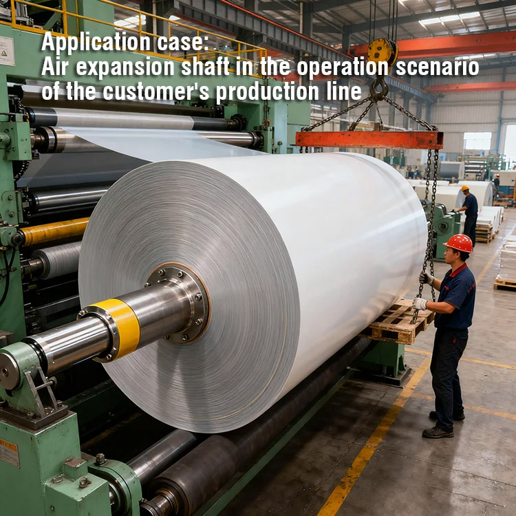
Unwind stands in industrial paper, film, and web processing applications demand precision braking systems that balance speed control, safety, and operational reliability. The air shaft has emerged as a critical component in high-performance pneumatic brakes designed specifically for these demanding environments. An air shaft functions as the rotating core element that delivers controlled pneumatic pressure to brake mechanisms, enabling smooth tension management and emergency stopping capability in unwind applications. Understanding how an air shaft operates within pneumatic brake systems is essential for maintenance teams, engineers, and procurement professionals responsible for line performance and worker safety.
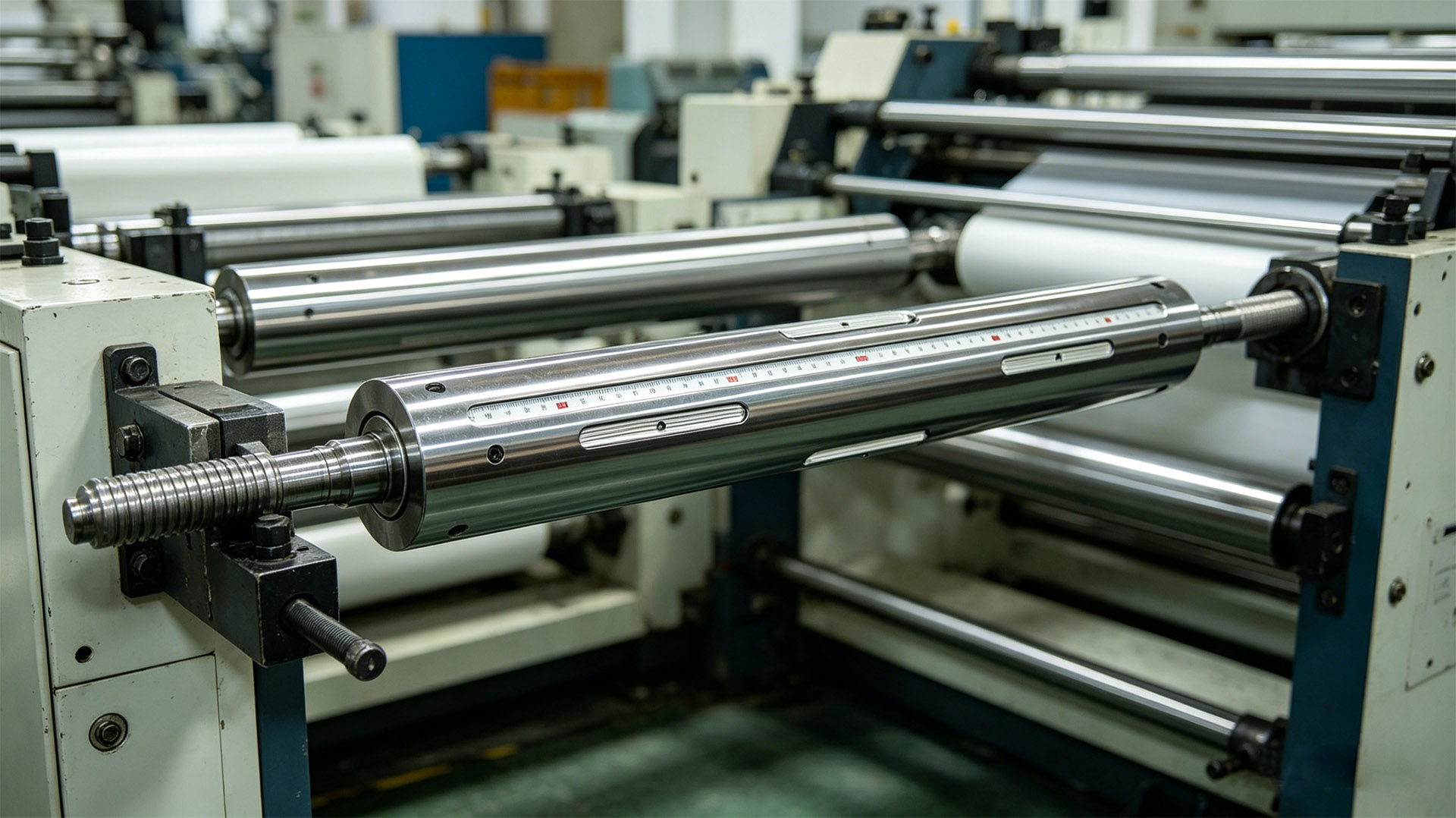
The integration of an air shaft into pneumatic brake systems represents a major advancement in unwind stand technology. Unlike mechanical or hydraulic alternatives, an air shaft enables instantaneous pressure modulation, proportional braking force, and the ability to release braking instantly when production resumes. This responsiveness is crucial for web material handling, where uncontrolled tension can lead to product waste, equipment damage, or safety incidents. Modern unwind stands equipped with high-performance pneumatic brakes featuring an air shaft deliver measurable improvements in operational uptime, material quality, and worker safety.
How Air Shaft Technology Powers Pneumatic Brake Performance
Core Operating Principle of the Air Shaft
An air shaft works by receiving regulated compressed air that enters through rotary union connections mounted on the shaft body. The air shaft channels this pressure internally through precisely designed ports and passages that communicate with brake actuators positioned around the shaft. As air pressure builds within the brake chambers, friction surfaces engage smoothly against the material being unwound, creating the braking force required to hold or slow the web. The key advantage of an air shaft design is that pressure can be adjusted in real time without stopping the machinery, enabling operators to fine-tune tension and braking response during production runs.
The rotary union that connects an air shaft to the stationary compressed air supply is engineered to withstand continuous rotation while maintaining an airtight seal. This sealed connection prevents pressure loss and contamination, ensuring that braking force remains consistent throughout the operating cycle. High-performance pneumatic brakes rely on an air shaft to deliver uniform pressure distribution, which translates directly into predictable, repeatable braking performance across extended production runs.
Pressure Modulation and Control Dynamics
An air shaft enables proportional pressure control through integrated regulators and pilot-operated valves that modulate air supply based on operator input or feedback from tension sensors. When an unwind stand needs to slow material flow, the air shaft allows pressure to increase gradually, preventing sudden jerking that could damage delicate films or papers. Conversely, when production speeds up, the air shaft system can release pressure smoothly, ensuring the brake does not drag unnecessarily. This dynamic control capability distinguishes high-performance pneumatic brakes with an air shaft from simpler spring-applied designs that offer only on-off functionality.
Real-world unwind operations benefit significantly from an air shaft's ability to maintain stable tension even as material density, width, or processing speed changes. Operators can dial in precise braking response, reducing material scrap and improving downstream process quality. The air shaft essentially functions as the nervous system of the pneumatic brake, translating control signals into smooth, proportional mechanical action.
Design Considerations and Material Selection for Air Shaft Systems
Structural Materials and Pressure Ratings
An air shaft must be manufactured from alloys that withstand repeated pressure cycling, mechanical stress, and the corrosive environments common in industrial production facilities. High-strength steel or aluminum alloys are standard choices, selected based on operational pressure requirements and expected service life. An air shaft designed for high-performance pneumatic brakes typically operates at pressures between 60 and 90 psi, with peak pressures potentially reaching 100 psi during emergency braking events. Material selection ensures that an air shaft will not fail under these loads while remaining cost-effective for industrial production.
The internal porting within an air shaft must be precision-machined to ensure consistent flow rates and pressure distribution. Any irregularities in an air shaft's internal passages can lead to uneven braking force, vibration, or pressure surges that compromise performance and accelerate wear. Manufacturers of high-performance pneumatic brakes invest heavily in quality control to verify that each air shaft meets dimensional tolerances and flow specifications before assembly into the complete brake system.
Sealing Technology and Maintenance Implications
An air shaft relies on dynamic seals at the rotary union to prevent air leakage and contamination ingress. Polyurethane and fluoroelastomer seals are commonly used because they resist abrasion, maintain flexibility across temperature ranges, and provide long service intervals. The design of seals around an air shaft is critical because even minor leakage reduces braking efficiency and increases compressed air consumption, raising operational costs. Maintenance teams must periodically inspect seals, replace them when wear becomes visible, and keep the rotary union area clean to extend the lifespan of the air shaft system.
Modern high-performance pneumatic brakes feature an air shaft with sealed rotary unions that minimize maintenance burden. Some designs incorporate grease-packed bearing assemblies that reduce the frequency of seal replacement and lower the total cost of ownership over the brake's lifetime.
Applications and Performance Outcomes in Unwind Stand Operations
Web Material Processing Use Cases
An air shaft pneumatic brake system excels in paper mills where continuous tension control is essential for producing consistent sheet quality. The air shaft's ability to modulate pressure allows operators to prevent paper breaks, reduce thickness variations, and maintain uniform winding density on large rolls. In film extrusion operations, where plastic film must be held at precise tension to avoid stretching or tearing, an air shaft equipped pneumatic brake provides the responsive control needed to protect delicate material. Converting operations for labels, laminates, and specialty films depend on the consistent, proportional braking force that only an air shaft system can deliver reliably.
Textile production also benefits from high-performance pneumatic brakes with an air shaft, particularly in facilities processing synthetic fibers or blended fabrics where material sensitivity is high. The ability to apply graduated braking force prevents fiber breakage and maintains the aesthetic quality of finished goods. An air shaft design enables these diverse applications to share a common braking platform, simplifying inventory management and standardizing maintenance procedures across multiple production lines.
Safety and Emergency Response Capability
Unwind stands equipped with air shaft pneumatic brakes provide immediate emergency stopping when operators detect hazards or machinery anomalies. The air shaft system can be designed with spring-applied, air-release configuration, meaning that loss of compressed air pressure automatically engages the brake fully, holding material in place and preventing runaway conditions. This fail-safe characteristic of an air shaft design is mandated by safety regulations in food, pharmaceutical, and high-speed packaging operations where worker protection is paramount. An air shaft brake system can stop a rotating unwind stand in fractions of a second, well within the response times required by industrial safety standards.
The integration of an air shaft into pneumatic brake architecture also simplifies integration with machine safety controllers and emergency stop systems. Maintenance and engineering teams can program an air shaft system to respond to pressure drops, speed anomalies, or sensor signals, enabling predictive maintenance and preventing cascading failures in complex production environments.
FAQ
What pressure range is typical for an air shaft in industrial pneumatic brakes?
Most industrial air shaft pneumatic brake systems operate between 60 and 90 psi under normal production conditions. Peak pressures during emergency braking may reach 100 psi or slightly higher depending on brake design and load requirements. An air shaft must be rated and tested to handle these pressures safely throughout its service life, typically 10 to 15 years of continuous operation in demanding unwind applications.
How often should an air shaft rotary union be inspected or serviced?
An air shaft rotary union should be visually inspected monthly for visible leakage, corrosion, or damage. Compressed air filters and regulators feeding the air shaft system should be serviced quarterly. Seal replacement intervals depend on operating hours and environmental conditions but typically range from two to five years. Regular maintenance of the air shaft assembly prevents pressure loss and ensures consistent braking performance across production runs.
Can an air shaft pneumatic brake system be retrofitted to existing unwind stands?
Many existing unwind stands can be retrofitted with modern air shaft pneumatic brake systems, though compatibility depends on shaft diameter, mounting configuration, and pressure requirements. A qualified engineer should assess the existing stand to determine if the air shaft system can be adapted without major structural changes. Retrofitting an air shaft brake often improves performance and safety compared to aging mechanical brakes while extending the productive lifespan of the machinery.

